As a reliable supplier of the 3722 silicon microphone, I'm excited to share with you the detailed installation method of this high - performance product. Silicon microphones have become an essential component in a wide range of applications, from consumer electronics to industrial devices, due to their small size, low power consumption, and excellent acoustic performance. The 3722 silicon microphone, in particular, stands out with its advanced features and reliable operation.
Understanding the 3722 Silicon Microphone
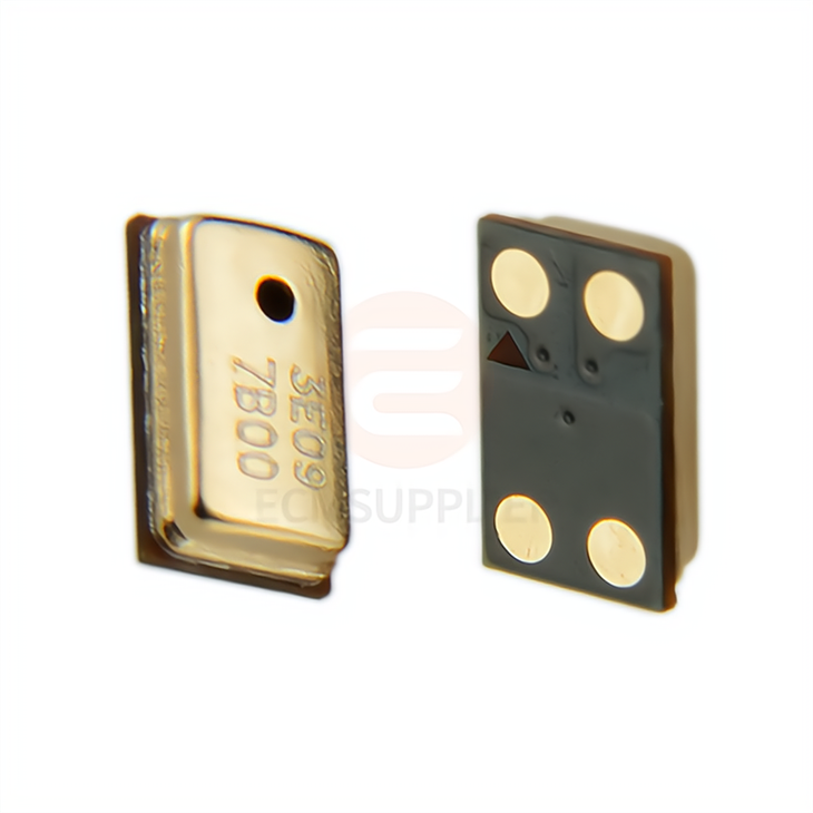
Before we dive into the installation process, let's briefly understand the key features of the 3722 silicon microphone. It is a MEMS (Micro - Electro - Mechanical Systems) based microphone that offers high sensitivity, wide frequency response, and low noise levels. These features make it suitable for various applications such as smartphones, tablets, smart speakers, and voice - controlled devices.
The 3722 silicon microphone is designed to provide clear and accurate audio capture, even in challenging environments. Its compact size allows for easy integration into different devices, and it is available in different packages to meet the specific requirements of various applications. To learn more about the 3722 silicon microphone, you can visit our product page 3722 Silicon Microphone.
Tools and Materials Required
To install the 3722 silicon microphone, you will need the following tools and materials:
- Soldering Iron: A soldering iron with a fine tip is required for soldering the microphone to the PCB (Printed Circuit Board). Make sure the soldering iron has adjustable temperature settings to prevent overheating the microphone.
- Solder: High - quality solder is essential for a reliable electrical connection. Choose a solder with a low melting point and good wetting properties.
- Flux: Flux helps to clean the surfaces of the PCB and the microphone pins, improving the soldering quality. Apply a small amount of flux to the soldering points before soldering.
- Tweezers: Tweezers are used to handle the small microphone and place it accurately on the PCB.
- Multimeter: A multimeter can be used to test the electrical connection after soldering to ensure that the microphone is working properly.
- PCB: The PCB should be designed to accommodate the 3722 silicon microphone. Make sure the PCB has the correct footprint and pads for the microphone.
Installation Steps
Step 1: Prepare the PCB
The first step in the installation process is to prepare the PCB. Clean the PCB surface using a PCB cleaner to remove any dirt, dust, or oxidation. This will ensure a good electrical connection between the microphone and the PCB.
Next, apply a small amount of flux to the pads on the PCB where the microphone will be soldered. The flux will help the solder to flow smoothly and form a strong bond.
Step 2: Place the Microphone
Using tweezers, carefully pick up the 3722 silicon microphone and place it on the prepared PCB. Make sure the microphone is aligned correctly with the pads on the PCB. Check the datasheet of the microphone for the correct orientation.
Step 3: Solder the Microphone
Once the microphone is in place, it's time to solder it to the PCB. Heat the soldering iron to the appropriate temperature (usually around 300 - 350°C). Touch the tip of the soldering iron to the pad on the PCB and the corresponding pin of the microphone simultaneously. Apply a small amount of solder to the joint until it forms a smooth and shiny connection.
Repeat this process for all the pins of the microphone. Be careful not to apply too much solder, as it can cause short - circuits. Also, avoid overheating the microphone, as it can damage the sensitive MEMS structure inside.
Step 4: Inspect the Soldering
After soldering, carefully inspect the joints to ensure that they are clean and free of any solder bridges or cold joints. A cold joint is a joint that has not been properly heated, resulting in a weak electrical connection. If you find any cold joints, reheat the joint and add a small amount of additional solder.
Step 5: Test the Microphone
Once the soldering is complete, it's time to test the microphone. Connect the PCB to a power source and an audio testing device. Use a multimeter to check the electrical connection and measure the output voltage of the microphone. You can also play some audio near the microphone and check if it can capture the sound correctly.
Considerations and Best Practices
- Electrostatic Discharge (ESD) Protection: The 3722 silicon microphone is sensitive to electrostatic discharge. Always use ESD - protected equipment and work on an ESD - protected surface when handling the microphone.
- Mechanical Vibration and Shock: Avoid subjecting the microphone to excessive mechanical vibration and shock during installation and operation. This can damage the MEMS structure inside the microphone and affect its performance.
- Environmental Conditions: The microphone should be installed in an environment with appropriate temperature and humidity levels. High temperatures and humidity can cause corrosion and other problems.
- Acoustic Design: Consider the acoustic design of the device when installing the microphone. Make sure there are no obstructions in front of the microphone's sound inlet, and the microphone is placed in a location where it can capture the sound effectively.
Related Products
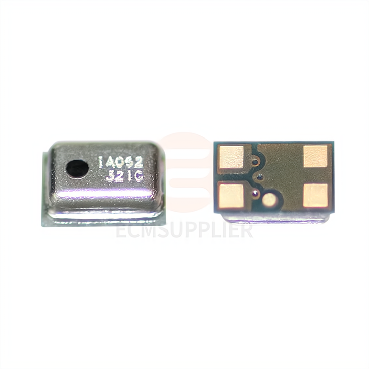
In addition to the 3722 silicon microphone, we also offer other high - quality silicon microphones, such as the 2718 Silicon Microphone and the 3729 Silicon Microphone Head MEMS. These products have their own unique features and are suitable for different applications.
Contact for Purchase and Consultation
If you are interested in purchasing the 3722 silicon microphone or have any questions about its installation or application, please feel free to contact us. Our professional sales team is ready to provide you with detailed product information and technical support. We can also offer customized solutions based on your specific requirements.
References
- Manufacturer's datasheet of the 3722 silicon microphone.
- PCB design guidelines for MEMS microphones.
- Soldering techniques and best practices for electronic components.


