As a supplier of the 3722 silicon microphone, I understand the importance of ensuring its functionality meets the highest standards. In this blog post, I will share some effective methods for testing the functionality of the 3722 silicon microphone, which will help you make informed decisions when considering purchasing this product.
1. Understanding the 3722 Silicon Microphone
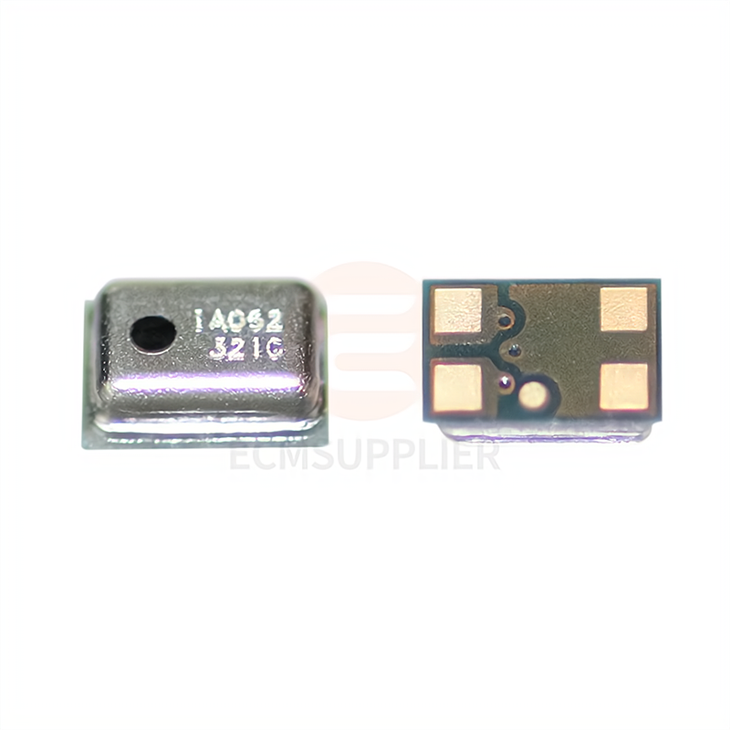
Before diving into the testing process, it's essential to have a basic understanding of the 3722 silicon microphone. The 3722 Silicon Microphone is a high - performance MEMS (Micro - Electro - Mechanical Systems) microphone known for its excellent acoustic performance, low power consumption, and small form factor. It is widely used in various applications such as smartphones, tablets, wearables, and IoT devices.
2. Preparation for Testing
2.1 Equipment
- Audio Signal Generator: This device is used to generate a wide range of audio signals with different frequencies and amplitudes. It allows you to simulate various real - world acoustic environments.
- Oscilloscope: An oscilloscope is used to display and analyze the electrical signals output by the microphone. It helps you visualize the waveform, amplitude, and frequency of the signals.
- Spectrum Analyzer: A spectrum analyzer can break down the audio signal into its frequency components, providing detailed information about the microphone's frequency response.
- Acoustic Chamber: An anechoic or semi - anechoic chamber is ideal for testing microphones as it minimizes external noise and reflections, providing a controlled acoustic environment.
2.2 Test Setup
- Mount the 3722 silicon microphone securely in the test fixture. Make sure it is properly aligned and positioned according to the manufacturer's specifications.
- Connect the microphone to the oscilloscope and spectrum analyzer using appropriate cables. Ensure all connections are stable and free from interference.
- Place the audio signal generator at a fixed distance from the microphone. The distance and angle should be consistent throughout the testing process to ensure accurate results.
3. Basic Functionality Tests
3.1 Sensitivity Test
Sensitivity is one of the most important parameters of a microphone. It measures the microphone's ability to convert acoustic energy into electrical energy.
- Set the audio signal generator to produce a pure sine wave at a specific frequency (e.g., 1 kHz) and amplitude (e.g., 94 dB SPL).
- Measure the output voltage of the microphone using the oscilloscope. Compare the measured output voltage with the manufacturer's specified sensitivity value.
- Repeat the test at different frequencies (e.g., 100 Hz, 10 kHz) to obtain a comprehensive understanding of the microphone's sensitivity across the audio spectrum.
3.2 Frequency Response Test
The frequency response of a microphone describes how it responds to different frequencies of sound.
- Use the audio signal generator to generate a sweep signal that covers the entire frequency range of interest (e.g., 20 Hz - 20 kHz).
- Record the output of the microphone using the spectrum analyzer. The spectrum analyzer will display the amplitude of the output signal at each frequency.
- Plot the frequency response curve by plotting the amplitude (in dB) against the frequency (in Hz). Compare the measured frequency response curve with the manufacturer's specified curve. Deviations from the specified curve may indicate issues with the microphone's performance.
3.3 Signal - to - Noise Ratio (SNR) Test
The signal - to - noise ratio is a measure of the quality of the microphone's output signal. It is defined as the ratio of the signal power to the noise power.
- First, measure the noise level of the microphone by turning off the audio signal generator. The noise level can be measured using the oscilloscope or spectrum analyzer.
- Then, turn on the audio signal generator to produce a signal at a specific level (e.g., 94 dB SPL). Measure the total output signal level.
- Calculate the SNR using the formula: SNR = 20 * log10 (Signal Level / Noise Level). A higher SNR indicates better microphone performance.
3.4 Distortion Test
Distortion occurs when the output signal of the microphone does not accurately represent the input signal.
- Generate a pure sine wave using the audio signal generator at a specific frequency and amplitude.
- Analyze the output signal of the microphone using the spectrum analyzer. Look for the presence of harmonic distortion components. Harmonic distortion is caused by non - linearities in the microphone's response.
- Calculate the total harmonic distortion (THD) using the formula: THD = (sqrt (sum of the squares of the harmonic amplitudes) / fundamental amplitude) * 100%. A lower THD value indicates better linearity and less distortion.
4. Advanced Tests
4.1 Directivity Test
Directivity refers to the microphone's ability to pick up sound from different directions.
- Rotate the microphone in a 360 - degree circle while keeping the audio signal generator at a fixed position.
- Measure the output of the microphone at different angles. Plot the directivity pattern by plotting the output amplitude (in dB) against the angle (in degrees).
- Compare the measured directivity pattern with the manufacturer's specified pattern. This test helps you understand how the microphone performs in different acoustic environments and applications.
4.2 Humidity and Temperature Tests
Microphone performance can be affected by environmental factors such as humidity and temperature.
- Place the microphone in a temperature - and humidity - controlled chamber.
- Conduct the sensitivity and frequency response tests at different temperature and humidity levels. For example, test the microphone at temperatures ranging from - 20°C to 60°C and humidity levels from 10% to 90%.
- Analyze the changes in the microphone's performance due to temperature and humidity variations. This information is crucial for applications where the microphone will be exposed to harsh environmental conditions.
5. Comparison with Other Microphones
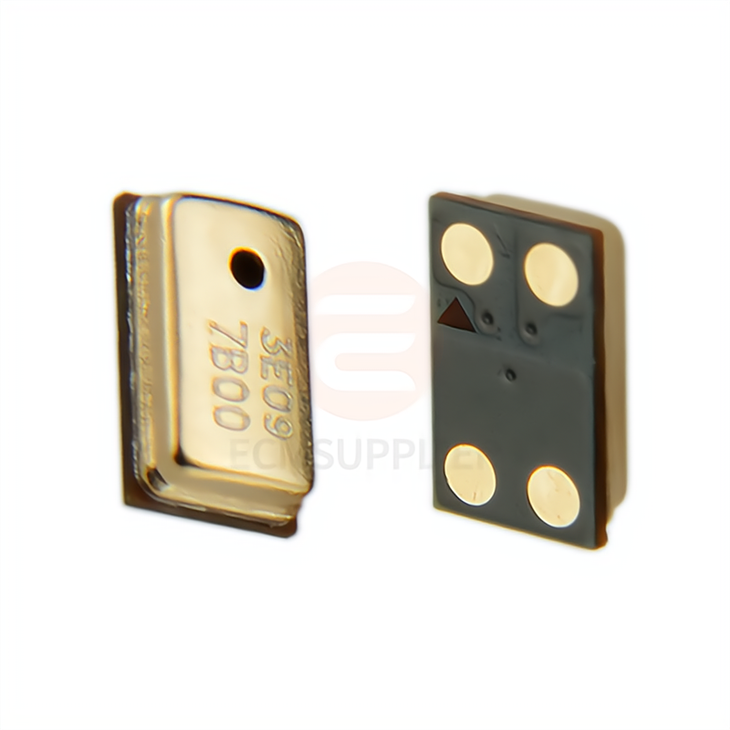
To further evaluate the performance of the 3722 silicon microphone, you can compare it with other similar microphones on the market, such as the 3729 Silicon Microphone Head MEMS and 2718 Silicon Microphone.
- Conduct the same set of tests on the 3722 silicon microphone and the other microphones under the same test conditions.
- Compare the test results, including sensitivity, frequency response, SNR, and distortion. This comparison will help you highlight the advantages and disadvantages of the 3722 silicon microphone and make more informed purchasing decisions.
6. Conclusion
Testing the functionality of the 3722 silicon microphone is a comprehensive process that requires careful preparation, proper equipment, and accurate measurement techniques. By conducting a series of basic and advanced tests, you can ensure that the microphone meets your specific requirements and performs well in real - world applications.
If you are interested in purchasing the 3722 silicon microphone or have any questions about the testing process, please feel free to contact us for further discussion and negotiation. We are committed to providing high - quality products and excellent customer service.
References
- Microphone Testing Handbook, XYZ Publishing
- MEMS Microphone Technology and Applications, ABC Press
- Audio Engineering Society (AES) Standards on Microphone Testing


