As an SMD microphone supplier, I understand that many customers may encounter difficulties when it comes to installing SMD microphones. In this blog post, I'll share a detailed guide on how to install an SMD microphone, covering everything from preparation to the actual installation process. Whether you're a professional electronics engineer or a hobbyist, this guide will help you complete the installation smoothly.
Preparation
Before you start the installation, it's crucial to gather all the necessary tools and materials. Here's a list of what you'll need:
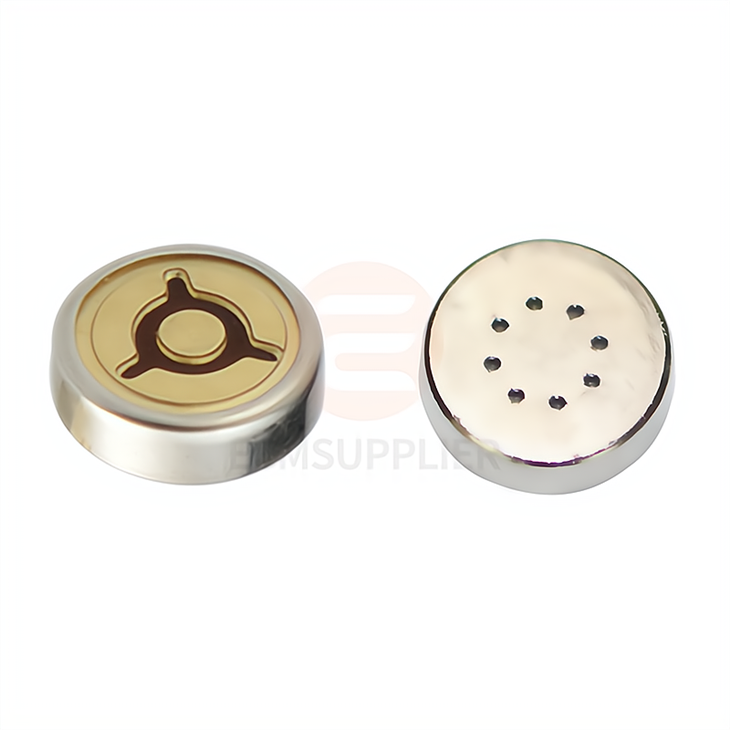
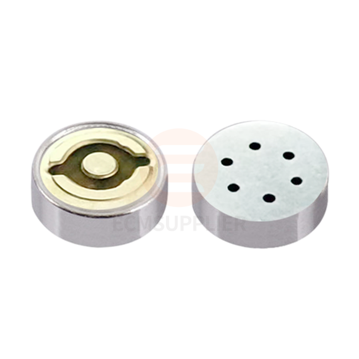
- SMD Microphone: We offer a variety of high - quality SMD microphones, such as the 3013 Patch Microphone Core Omnidirectional, 4013 SMT Microphone Capsules, and 4013 Patch Microphone Head All Directional Patch Mic. Choose the one that best suits your project requirements.
- Soldering Iron: A good soldering iron with a fine tip is essential for precise soldering. Make sure it has adjustable temperature settings to avoid overheating the components.
- Solder: Use high - quality lead - free solder with a small diameter, usually around 0.5mm - 0.8mm.
- Flux: Flux helps to improve the wetting of the solder and ensures a better connection. You can use liquid or paste flux.
- Soldering Station: This provides a stable working environment and helps to control the temperature accurately.
- Desoldering Pump or Braid: In case you make a mistake during soldering, these tools can be used to remove the excess solder.
- Magnifying Glass or Microscope: Since SMD components are very small, a magnifying glass or microscope will help you see the details clearly.
- Antistatic Mat and Wrist Strap: To prevent electrostatic discharge (ESD) from damaging the sensitive SMD microphone, use an antistatic mat and wear a wrist strap.
PCB Inspection
Before installing the SMD microphone, carefully inspect the printed circuit board (PCB). Check for any damaged traces, holes, or other defects. Make sure the pads on the PCB where the microphone will be soldered are clean and free of oxidation. If there is any dirt or oxidation on the pads, you can use a PCB cleaner or a small amount of isopropyl alcohol to clean them.
Positioning the Microphone
- Read the Datasheet: First, refer to the datasheet of the SMD microphone to determine its pinout and orientation. The datasheet will also provide information on the recommended soldering temperature and time.
- Align the Microphone: Use tweezers to pick up the SMD microphone and place it on the corresponding pads on the PCB. Make sure it is correctly aligned with the markings on the PCB. You can use a magnifying glass or microscope to ensure accurate alignment.
- Tack - Solder One Pin: Once the microphone is in position, heat one of the pins with the soldering iron and apply a small amount of solder to hold the microphone in place. This will prevent it from moving during the soldering of the remaining pins.
Soldering the Microphone
- Apply Flux: Apply a small amount of flux to all the pads and pins of the microphone. Flux will help the solder flow better and improve the quality of the solder joints.
- Solder the Pins: Heat each pin of the microphone one by one with the soldering iron. Apply a small amount of solder to the tip of the soldering iron and then touch it to the pin and the pad simultaneously. The solder should flow smoothly and form a good connection between the pin and the pad. Make sure not to apply too much solder, as this can cause short - circuits.
- Check the Solder Joints: After soldering all the pins, visually inspect the solder joints under a magnifying glass or microscope. The solder joints should be shiny, smooth, and free of cracks or cold joints. If you find any problems, use a desoldering pump or braid to remove the excess solder and re - solder the joint.
Cleaning the PCB
After soldering, clean the PCB to remove any flux residue. Flux residue can attract dust and moisture, which may cause corrosion over time. You can use isopropyl alcohol and a soft brush to clean the PCB. Gently brush the PCB to remove the flux residue, and then dry it with a clean cloth.
Testing the Microphone
Once the SMD microphone is installed and the PCB is clean, it's time to test the microphone. Connect the PCB to a power source and an audio amplifier or a test circuit. Speak or make some noise near the microphone and check if the audio signal can be detected. If there is no signal or the signal is weak, check the solder joints again to make sure there are no loose connections.
Troubleshooting
If you encounter problems during the installation or testing process, here are some common issues and solutions:
- No Audio Signal: Check the solder joints for any open circuits or short - circuits. Make sure the microphone is correctly powered and connected to the audio circuit.
- Weak Audio Signal: This could be due to poor solder joints, incorrect biasing, or a damaged microphone. Check the solder joints and refer to the datasheet for the correct biasing voltage.
- Interference or Noise: Make sure the PCB layout is designed to minimize electromagnetic interference (EMI). You can also add decoupling capacitors near the microphone to filter out the noise.
Conclusion
Installing an SMD microphone requires patience, precision, and the right tools. By following the steps outlined in this guide, you can successfully install an SMD microphone on your PCB. Remember to always refer to the datasheet of the microphone for specific instructions and recommendations.
If you're interested in purchasing high - quality SMD microphones for your projects, we're here to help. Our team of experts can provide you with detailed product information and technical support. Contact us to start a procurement discussion and find the best SMD microphone solutions for your needs.
References
- Electronic Components Datasheets
- Soldering Techniques and Best Practices Guides
- PCB Design and Assembly Manuals


